Framo’s new submerged electric liquid gas fuel pump combines our expertise in hydraulic submerged cargo pumps and electric seawater lift pumps into a single, efficient design.
All external connections are located on the top plate of the pump, from which the pump is suspended during operation. The pipe stack integrates the fuel discharge pipe and power transmission into one component, eliminating the need for hanging electric cables and providing mechanical protection for the integral power transmission. Additionally, the pump and pipe stack are enclosed by a caisson pipe, which further reduces mechanical strain on the pump components caused by sloshing. The caisson pipe also significantly reduces the need for radial fixed supports in the tank walls.
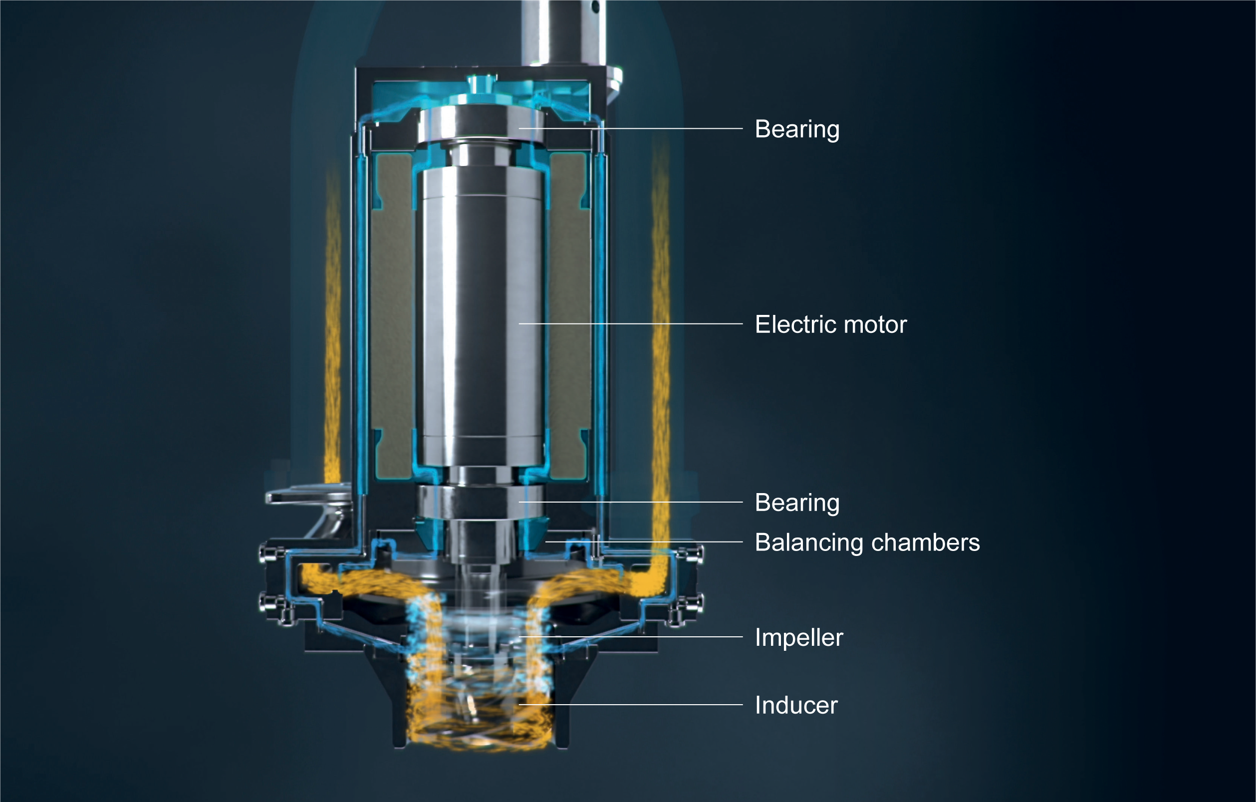
With no seals, the entire pump operates fully immersed. The rotating assembly is thrust-balanced by continuously adjusting the allowed wear ring leak flow and pressure loss. The same flow is used to cool the electric motor before returning to the suction side of the pump. The generation of boil-off gas is further reduced by fitting a highly efficient, custom-built electric induction motor. The Framo SLG pump is versatile, fitting seamlessly into any tank configuration.
Pump head
The SLG features an optimised flow path, striking the ideal balance between stage count and overall system efficiency. Leveraging our renowned double volute configuration enhances efficiency during off-design operation. The optimised inducer significantly reduces suction cavitation and the NPSH requirement. The compact design reduces cryo sump height requirements, thus minimising head space.

Motor
Framo SLG pump is powered by a custom-built 400V electric induction motor, utilising a VFD/VSD (Variable Frequency/Speed Drive) to reach its peak rated speed of 7000 rpm. Tested and validated for cryogenic temperatures at the Framo factory, the motor operates with an impressive efficiency of 96% at peak continuous power.
Cooling
In the volatile environment of liquid gas fuel storage, minimising heat transfer is crucial. The Framo SLG pump uses process flow to cool the motor unit, eliminating the need for an external cooling mechanism. Pressurised flow over the wear rings is directed into the motor, dissipating heat in the air gap between the stator and rotor. This cooled flow is then returned to impeller suction side via a conduit, maximising heat transfer out of the tank through the discharge flow. At peak power, only a fraction of generated heat is transferred into the tank.

TEM (Thrust Equalising Mechanism)
Operating at a minimum temperature of -196°C, traditional lubricants are inadequate for the Framo SLG’s needs. Given the poor lubricating properties of liquid gases and the fully submerged rotating assembly, motor shaft bearings face the risk of premature failure. Our dynamic TEM maintains the equilibrium of thrust forces by manipulating pressure loss over wear rings and a balancing orifice. This ensures longevity and reliability throughout the SLG’s lifetime.
Particle straining
The Framo SLG pump features a robust particle straining system to guard against pollution. Starting with a first barrier strainer at the suction or suction line, followed by a second barrier centrifugal separation, and finally, a third barrier wear ring gap. This layered approach ensures protection from clogging or erosion, maintaining smooth operation.
Pipe stack and power transmission
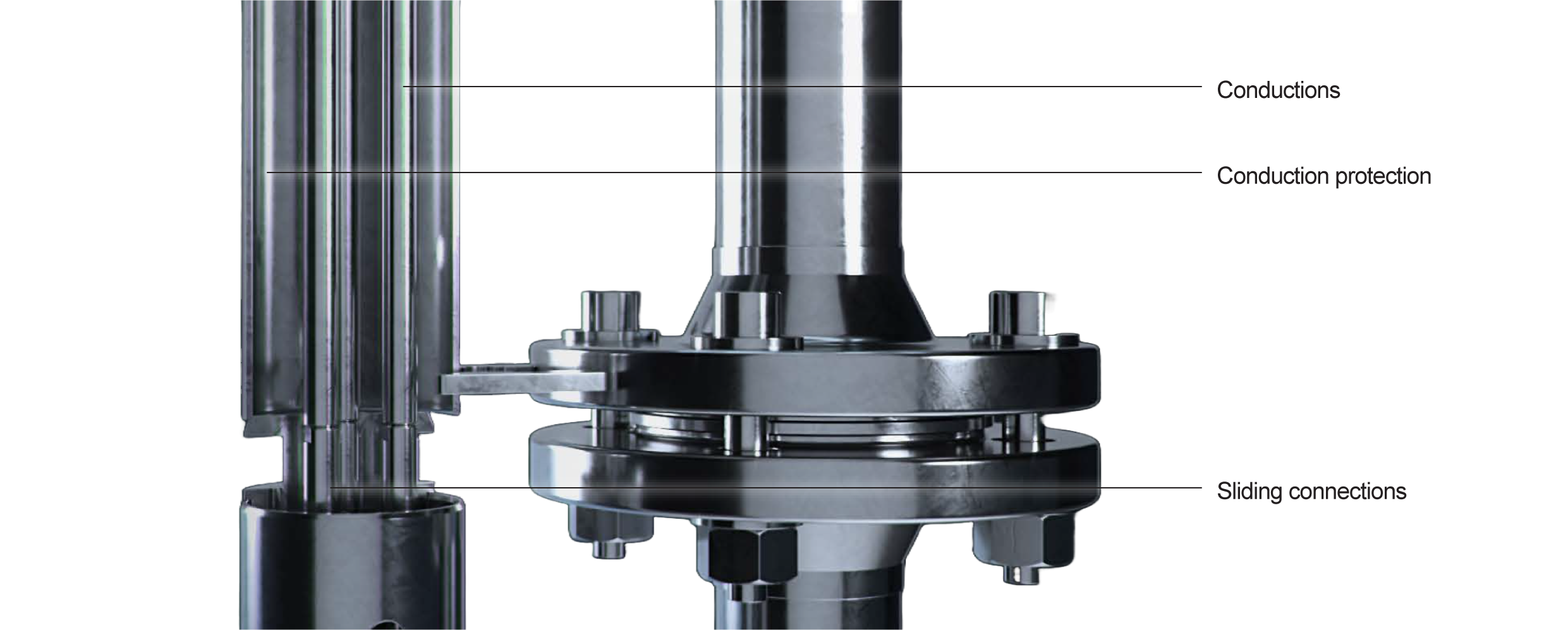
Our versatile pipe stack assembly, with sections spanning 1 m to 6 m, features three conductor rods spaced at 120-degree intervals. The conductors and their protective pipe are allowed to move axially independently of the fuel discharge pipe, countering differing temperature gradients. The fuel discharge pipes are flanged, while the conductor pipe has a male/female sliding connection. The three conductors have spring-loaded male/female stab-in connectors on each end, ensuring a stable and reliable phase connection. Similar connections are used to terminate the conductors to the motor and feedthrough.

Top plate connections
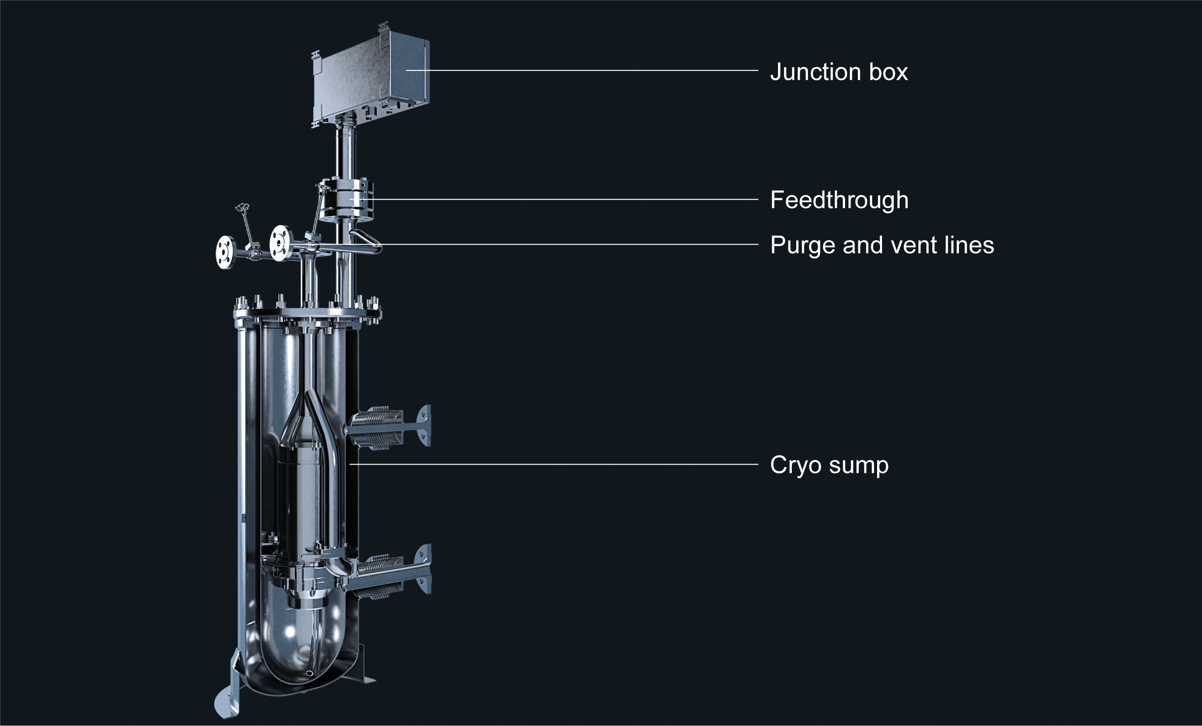
All pump operation connections, including discharge flange, power transmission feedthrough, and junction box, are located on the top plate. Additional connections, like purge/vent lines and instrumentation, can be added upon request, reducing tank penetrations. Junction box and feedthrough meet IP, IEC, Atex, Ex, and class requirements.
Cryo sump
For in-line or tank connection space (TCS) mounting, Framo supplies a vacuum-insulated cryo sump with foil insulation to significantly reduce thermal losses. Its top cover consolidates all connections for easy access. all connections for easy access.
Rune Sakslo
Jens Mildestveit
Download brochure
Stay updated
Contact form
Get the latest news and product information in your inbox.
Thank you for contacting us
We will get back to you as soon as possible

